Logic Design for Array-Based Circuits
by Donnamaie E. White
Copyright © 1996, 2001, 2002, 2008, 2016 Donnamaie E. White , WhitePubs Enterprises, Inc.
- Table of Contents
- Preface
- Overview
- Chapter 1 Introduction
- Chapter 2 Structured
Design Methodology
- Chapter 3 Sizing the
Design
- Functional Specification - A Closer Look
- Review the Available Arrays
- Architectual Specification or Hardware Specification
- Array Sizing
- Cell Capabilities
- Array Architecture
- Netlist
- Example: AMCC Interface Options
- Example - AMCC Arrays - Power Supply Options
- Interface Cell Functionality
- Examples
- Internal Cell Functionality
- Multi-Cell Macros
- Hard and soft macros
- Refining Interface Requirements
- Adding Extra Power and Ground Macros
- Dual-Function I/O Macros
- Example - Simultaneously Switching Outputs
- Thermal Diodes
- The AMCC Speed Monitor
- Final Interface Cell Utilization
- Drivers
- Exercises
- Chapter 3 Appendix = Case Study in Sizing a Design
- Chapter 4 Design Optimization
- Chapter 5 Timing Analysis for Arrays
- Chapter 6 External Set-up and Hold Times
- Chapter 7 Power Considerations
- Case Study: DC Power Computation
- Case Study: AC Power Computation
- Chapter 8 Simulation
- Case Study: Simulationest
- Chapter 9 Faults and Fault Detectiond Output
- Chapter 10 Design Submission
- ASIC Glossary
Sizing the Design - Selecting the Array
Refining Interface Requirements
When the interface types and their power supply requirements are documented and one or more arrays chosen as candidates for the final selection, the interface require ments must be refined. There are several conditions under which additional power or ground pads will need to be added to an array beyond the fixed power and ground pads provided. These include:
-
simultaneously switching outputs,
-
package restrictions,
-
high-speed signal isolation and
-
ECL - TTL isolation.
Simultaneous switching TTL or ECL outputs is a potential source of system noise, which can be reduced by the addition of TTL VCC - TTL Ground pairs and/or ECL VCC.
Some arrays require that drivers be placed next to ground. Others require that a ground exist between simultaneously switching TTL outputs and ECL inputs, or between any TTL output and an ECL input. Isolation of CMOS inputs from the faster switching TTL and ECL signals may also be required. When a fixed ground is not available, then one must be added. The design rules for any array series are called out in the Design Manual for the array.
Variable Requirements for Power and Ground
Bipolar arrays require that all fixed power and ground be used or bonded out to the package. Additional power and grounds are based on simultaneously switching out puts or isolation requirements.
CMOS arrays have some or all of their fixed power and ground pads under user -placement control. The vendor provided a list of how many would need to be used depending on the signals used by the design. This type of flexibility is detrimental to standard packaging; it is time consuming and expensive.
In spite of the drawbacks, recent BiCMOS designs have returned to this approach, providing the minimal number of power and grounds and allowing other fixed-position power and grounds to go unbonded (unconnected). The criteria for requiring that these fixed positions be used or that additional power and grounds be added is based on the number and types of interface macros used.
When the power busses supporting the internal core are isolated from the busses supporting the peripheral I, O or I/O cells, noise feedback due to output switching is minimized. The threshold and reference voltage generators for the logic array inter nal cells and I, O and I/O cells should also be independent to insure steady operation.
Adding Extra Power and Ground pads
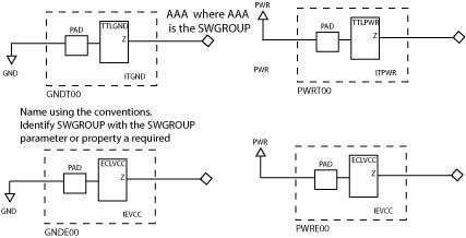
Adding a power pad or a ground pad to an array can be accomplished by placing a power or ground macro on the desired pad (array-specific procedure. AMCC arrays use the ITPWR (+5V), ITGND (0V) and IEVCC (ECL VCC) macros to add power or ground. (See Figure 3-6.) For standard reference ECL, IEVCC represents a ground pad. For +5V REF ECL, IEVCC represents a power pad.
Figure 3-6 Added power and Ground macros (AMCC)

The macro only uses the PAD portion of the input cell.
Note: When placing an IEVCC, ITPWR or ITGND macro, the macro must be interspersed with the simulataneously switching outputs (SSOs) it supports. On the Q20000T array, and any other array with packages that contain internal power-ground planes, the macro must be placed on a PAD that connects to the internal plane if at all possible. Placing it on a PAD that must connect to a package pin requires a custom DUT board for test.
The IEVCC has the input to the PAD grounded (wire pointing down) for standard-reference ECL (circa 1995). The wire is pointing up for +5V Ref ECL. The output in both cases is terminated.
IEVCC is GROUND macro for STD-REF ECL and is a POWER macro in a +5V REF ECL.
For ITPWR, ground the input pin with the wire pointing up. For ITGND, ground the input pin with the wire pointing down. Terminate the output in both cases.
Copyright © 1996, 2001, 2002, 2008, 2016 Donnamaie E. White , WhitePubs
Enterprises, Inc.
For problems or questions on these pages, contact [email protected]