Logic Design for Array-Based Circuits
by Donnamaie E. White
Copyright © 1996, 2001, 2002, 2008, 2016 Donnamaie E. White, WhitePubs Enterprises, Inc.
- Table of Contents
- Preface
- Overview
- Chapter 1 Introduction
- Chapter 2 Structured Design Methodology
- Chapter 3 Sizing the Design
- Chapter 3 Appendix = Case Study in Sizing a Design
- Chapter 4 Design Optimization
- Chapter 5 Timing Analysis for Arrays
- Chapter 6 External Set-up and Hold Times
- Case Study: Preventing Hold Violations Due To Clock Skew
- Computing Hold Time in the Register Example
- Minimum Library (Q5000 Series)
- Military Library (Q5000 Series)
- Exercises
- Chapter 7 Power Considerations
- Case Study: DC Power Computation
- Case Study: AC Power Computation
- Chapter 8 Simulation
- Case Study: Simulation
- Chapter 9 Faults and Fault Detection
- Chapter 10 Design Submission
- ASIC Glossary
External Set-Up and Hold Times
Last Edit July 22, 2001
Introduction
When the input to the data (D) or the clock (C) or both pins on a flip/flop or a latch are supplied from an external signal, then the external set-up and hold times must be computed. The computations must be for the worst-case and account for processing skew. The worst-case may be the worst-case maximum conditions or the worst-case minimum conditions.
Hold time violations are a concern wherever two storage elements interface with each other and are clocked by different drivers. An example structure is parallel-clocked register flip/flops driven by multiple clock macros. Any multiple clock organization or clock distribution tree is subject to this design hazard.
The error occurs when the Q output of one flip/flop (or latch) directly feeds the D input of another. If the clock to the second flip/flop is delayed due to tracking or skew, the D input may change during the set-up/hold window. This can be avoided by using the guidelines and design checks described in this chapter. (See the Case Study: Preventing Hold Violations Due to Clock Skew.)
To meet design submission requirements, both the maximum worst-case and the minimum worst-case equations need to be computed to determine the worst-case window for external set-up and hold times for the specified operating conditions. Both rising edge and falling edge input path propagation must be evaluated. For deeply-nested paths, consult the array vendor for other effects that must be considered.
Figure 6-1 illustrates the delay paths. The data delay path is TD; the clock delay path is TC. Depending on the methods used to specify macro timing, the data and clock paths may need to be divided into interface and internal macro components.
Results computed or derived from simulations using Front-Annotation data cannot be considered as the circuit specification. Those derived from Back-Annotation are considered to be the specification.
Figure 6-1 External Set-Up And Hold - Clock And Data Paths

There may be no internal macros in the data or the clock path or both, leaving the interface macro and the extrinsic loading as the only components in the paths. There may be multiple internal macros in a clock buffer tree while the data path is unloaded, or the data path may be heavily loaded while the clock path remains relatively simple.
The relative loading between these two paths will determine whether the set-up or hold time is negative or positive and how large the set-up and hold window will be. The intrinsic set-up and hold time of the latch or flip/flop is another factor in the equation.
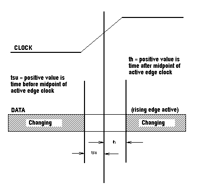
Figure 6-2 External Set-Up And Hold Times - Interpretation

Figure 6-2 diagrams the definitions of positive set-up and hold times. Data must be held stable relative to the associated clock during these times. The time span indicated by the set-up and hold times is referred to as a timing "window".
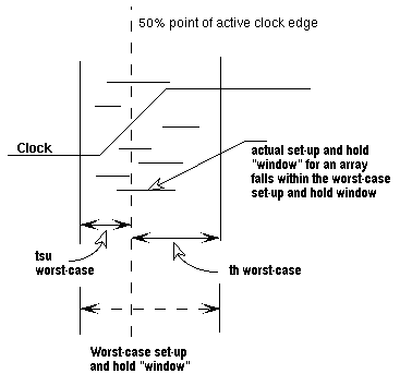
The term window is used since the external set-up and hold computations will produce a wider timing range than will be exhibited by any single die. For one set of operating conditions, the set-up time is computed assuming that the data path is worst-case maximum and the clock is worst-case minimum. The hold time reverses this and is computed assuming that the clock path is worst-case maximum and the data path is worst-case minimum. The resulting range is designed to encompass all extremes of voltage, temperature and process. (See Figure 6-3.)
Figure 6-3 Worst-Case Range

Figure 6-3 diagrams the worst-case window produced from the maximum external set-up time and the maximum external hold time. The conditions under which these two values are computed are inconsistent and contradictory with each other, thereby ensuring that the set-up and hold timing "window" for the same two signals for any single array is contained within the computed range.
.
Copyright © 1996, 2001, 2002, 2008, 2016 Donnamaie E. White , WhitePubs
Enterprises, Inc.
For problems or questions on these pages, contact [email protected]