Logic Design for Array-Based Circuits
by Donnamaie E. White
Copyright © 1996, 2001, 2002, 2008, 2016 Donnamaie E. White , WhitePubs Enterprises, Inc.
- Table of Contents
- Preface
- Overview
- Chapter 1 Introduction
- Chapter 2 Structured
Design Methodology
- Chapter 3 Sizing the
Design
- Functional Specification - A Closer Look
- Review the Available Arrays
- Architectual Specification or Hardware Specification
- Array Sizing
- Cell Capabilities
- Array Architecture
- Netlist
- Example: AMCC Interface Options
- Example - AMCC Arrays - Power Supply Options
- Interface Cell Functionality
- Examples
- Internal Cell Functionality
- Multi-Cell Macros
- Hard and soft macros
- Refining Interface Requirements
- Adding Extra Power and Ground Macros
- Dual-Function I/O Macros
- Example - Simultaneously Switching Outputs
- Thermal Diodes
- The AMCC Speed Monitor
- Final Interface Cell Utilization
- Drivers
- Exercises
- Chapter 3 Appendix = Case Study in Sizing a Design
- Chapter 4 Design Optimization
- Chapter 5 Timing Analysis for Arrays
- Chapter 6 External Set-up and Hold Times
- Chapter 7 Power Considerations
- Case Study: DC Power Computation
- Case Study: AC Power Computation
- Chapter 8 Simulation
- Case Study: Simulationest
- Chapter 9 Faults and Fault Detectiond Output
- Chapter 10 Design Submission
- ASIC Glossary
Sizing the Design - Selecting the Array
Examples
The Q20000 Series arrays support a bidirectional macro that sits on two I/O cells, unlike the single-cell approach of the Q5000 Series. In this case, the internal macro routing eliminates the need for two sets of test vectors or an extra bonded-out pad.
Each bidirectional macro also contains either an IEVCC pad (ECL VCC) or an ITGND (TTL GROUND) pad. (Refer to "Added power and grounds" for a discussion of pad -plane interconnections for added power and ground pads.)
Internal Cell Functionality
The logic (bipolar) and basic (BiCMOS) cells are organized to provide logic functions such as basic logic gates and buffers, high-fan-out drivers, EXOR and EXNOR net works, gate networks, multiplexors, decoders, latches, and flip/flops.
These cells can support a 3:1 MUX-D flip/flop combination, triple latch-common clock, triple 2:1 MUX-common select and dual D F/Fs. As stated before (see "Cell struc ture"), the number of cells required for any of these functions will vary by array series.
The number of cells required to implement a function depends on the component mix present in the cell and that required by the function. Arrays are designed for a specific set of applications or targets and base array design is optimized for those applications.
An array cell size may be divisible so that half-cell macros are possible, which also allows sizes such as 4.5 cells. A cell may be designated as the smallest divisible or addressable unit (SAU), in which case a one cell macro is the smallest macro allowed.
Multi-Cell Macros
Groups of internal and/or interface cells can also be combined into large multi-cell macros for higher functionality. The larger multi-cell macros, named MSI macros by AMCC, interconnect components spread across several cells more efficiently than the schematic interconnection of the equivalent function formed from basic macros. The result is a denser functionality with the resultant speed improvement.
Design density, measured by the cell utilization per functionality, can be increased by 20-40% while reducing design partitioning and macro conversion efforts. The large MSI macros include MSI and LSI functions.
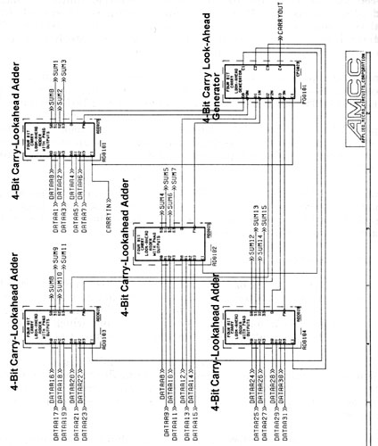
Example MSI macros are 6-bit comparators, 4-bit carry-look ahead adders and their companion carry-look-ahead generator, 4-bit up and down counters, 4-bit registers, 6-bit comparators and 8-bit latches. Different array series offer different MSI mac ros.
The simple and MSI macros available with a specific array series are documented, along with any use or placement restrictions, in the appropriate Design Guide or Design Manual. Always refer to the latest version of these manuals when performing an evaluation.
Hard and Soft Macros
There are two types of MSI or multi-cell macros. One type is hard, where the cell interconnect is treated as one large macro and no variations in layout are permitted. The other type is soft, where the cells composing the macro have a preferred, speci fied-to layout pattern but which requires the interconnect to be routed as if it were any other interconnect net.
The MSI macros in the Q5000 Series were originally designed to allow placement in several different configurations to facilitate the auto-place algorithm (best-fit ap proach), while closely maintaining the specified performance for the macro. This is a soft-macro. A preferred placement is documented.
The problems in improper placement, which invalidates the timing specifications and therefore, the simulation model, and the problems in net weighting and prioritizing the internal nets to the router, so that the interconnect delay could be kept minimal, make the soft MSI macro approach unattractive.
Both the BiCMOS Q14000 and Q20000 Series MSI macros use hard-macros, where an MSI macro is laid-out as a single multi-cell unit and handled by the placement soft ware as an inflexible black box. Hard-macros facilitate automated placement. Future AMCC arrays will use the hard macro approach. Figure 3-5 shows an MSI-based 16 -bit adder.
Figure 3-5 16-Bit MSI Adder (1994)
Copyright © 1996, 2001, 2002, 2008, 2016 Donnamaie E. White , WhitePubs
Enterprises, Inc.
For problems or questions on these pages, contact [email protected]