Logic Design for Array-Based Circuits
by Donnamaie E. White
Copyright © 1996, 2001, 2002, 2008, 2016 Donnamaie E. White , WhitePubs Enterprises, Inc.
- Table of Contents
- Preface
- Overview
- Chapter 1 Introduction
- Chapter 2 Structured
Design Methodology
- Structured Design Methodology
- Review of the Available Arrays
- Initial Sizing of the Circuit
- Create the Preliminary Macro Schematic (when schematics are used)
- Compute the Path Propagation Delay
- Compute the Estimated Power
- Pre-Simultation Steps
- Simulation
- Fault Grading
- Design Submission Through Prototype
- Chapter 3 Sizing the Design
- Chapter 3 Appendix = Case Study in Sizing a Design
- Chapter 4 Design Optimization
- Chapter 5 Timing Analysis for Arrays
- Chapter 6 External Set-up and Hold Times
- Chapter 7 Power Considerations
- Case Study: DC Power Computation
- Case Study: AC Power Computation
- Chapter 8 Simulation
- Case Study: Simulationest
- Chapter 9 Faults and Fault Detectiond Output
- Chapter 10 Design Submission
- ASIC Glossary
Structured Design Methodology
Simulation
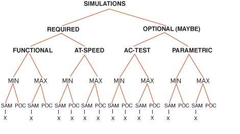
Once the circuit has been checked for design rule violation, sizing, power, package fit, optimization, functionality and other non-simulation dependent checking, the simulations required by the array vendor may be performed. There are several types of simulations: functional (all etch is connected without SA0, SA1 faults); at-speed (the array-implemented design runs at the specified maximum operating frequency of the circuit); AC test (path propagation delay) and parametric (VIH, VIL). The array vendor may specify the simulations, formats required, and vector rules to be followed.
Modular Simulations - Debug Only
During logical debug of the original design it is better to simulate modular segments of the circuit, verifying basic logical operation and debugging the immediately obvious design errors. Once the circuit is considered to be a successful logical design, then perform the functional simulation that will form the basis of the test vectors submitted with the design. Multiple fragmented functional simulations cannot be submitted.
Functional Simulation
The object of functional testing is to detect a single SA1 (stuck-at-1) or SA0 (stuck-at-0) fault in the circuit if one exists. This ideally requires sufficient vectors to "cover" all possible SA1 and SA0 fault locations. The percentage of coverage is the fault grade of the vector set. For a high fault-grade score (95% and up), other types of circuit failures are assumed to be "covered".
Functional test vectors are initially created from the functional simulation sampled results file. Functional simulations are run using Front-Annotation or Intermediate-Annotation with timing checks enabled. They are re-executed when Back-Annotation is available. It is the Back-Annotated simulation result file that goes to test.
The functional vector set for a circuit should detect any single fault occurring on a single path. In theory, triple faults, odd faults of 5, etc., per path are covered by the vectors detecting single faults provided the faults do not mask each other. Even-numbered sets of faults on a path (double faults, quad faults, etc.) are assumed to mask each other and not to be detectable. The probability of multiple faults on a path is significantly less than the probability of a single fault. (Multiple faults that signal a catastrophic failure are detected within the basic wafer screening.)
Figure 2-4a Simulations - Types And Forms
| SAMPLED | PRINT ON CHANGE |
|||
| MAX | MIN | MAX | MIN | |
| FUNCTIONAL | X | X | ||
| AT-SPEED | X | X | X | X |
| AC TEST | X | X | X | X |
| PARAMETRIC | X | X |
Figure 2-4b Circuit Simulation Requirements
Redundant circuit logic will cause some faults to be masked (prevent their detection) and should be avoided. Where redundancy is desired for other reasons, the designer should add test points to make masked faults visible.
One extreme approach used to develop functional vectors is to cycle all inputs and outputs through all combinations of 1-0 and 0-1 transitions as a first check after initialization. (Theoretically, this should cycle all internal nodes in a combinatorial circuit as well.) This 2n (where n = number of inputs) brute force approach is not necessary.
Minimum vector test sets and minimum vector test sequences will cover 100% of all observable faults. A fault cannot be detected by any test methodology if it is a masked fault. A masked fault cannot be seen at a primary output due to redundancy in the logic. Logic minimization is therefore a requirement if high fault grade scores are desired.
The functional simulation vectors may have been developed for an earlier technology version of the array circuit or may be developed from scratch. They need to be constructed in pages (AMCC uses a 4K or an 128K page depending on the tester), begin with initialization of the array, and initialize periodically within the page between test modules.
Begin by initializing every I/O pin (preferred initialization is within 25 - 100 simulation steps, depending on array size). Proceed to "home" the circuit
For testability, a master reset or master set is desirable since it will allow a circuit to be placed in a known state quickly. For circuits that combine reset or set with non-resettable logic, the flip/flops and latches that are not cleared by the set or reset should be initialized after the set or reset has executed and the components settled. A circuit will need to be placed in a known state between groups of tests, at tester page boundaries and before any long or complex test.
Functional simulation execution
Functional simulations must be done for the maximum and minimum worst-case timing and are sampled with a step long enough to ensure that all changes caused by the controlling data or clock signal have stabilized. (AMCC uses a step of 100ns.) The rule of thumb is to measure the longest path in the circuit, compute its worst-case maximum time delay, add 50ns and round to the nearest 100. For BiCMOS and bipolar arrays, 100ns is more than adequate.
The 100ns step size equates to 50MHz, the limit for the SENTRY tester. Different vendors may specify different step size approaches but the necessity of all signals being stable will remain.
Functional simulation results for the maximum and minimum libraries should be compared as a check on hazards and races. The results for the minimum library should match those obtained with the maximum library. If they do not match, stop and evaluate why they do not.
Table 2-10 Functional Simulations
| minimum worst-case | maximum worst-case |
|---|---|
|
sampled |
sampled |
Simulation Outputs
Each simulator produces a data file or a list file that represents the signals the designer specified and the time step at which they were recorded. Most provide a waveform of the results as well. The formats of these output files are not standardized. To submit them to the array vendor, some reformatting must take place.
Reformatting Simulation Outputs
To allow vector format checking and to simplify test transfer, AMCC developed the AMCCSIMFMT (AMCC simulation format) program. It reformats the output of the logical simulator into a form acceptable to AMCC test and to programs that need to read the files. (This standard format allows the simulation sampled output file to be used as a data input file to other software.) Each supported EWS and netlister has a unique AMCCSIMFMT program.
Vector Rules Checking
The AMCC Vector Rules Checker (AMCCVRC) can be run against any AMCCSIMFMT (AMCC Simulation Format) sampled simulation output file from any simulator. AMCCVRC will issue a count of the number of test vectors and simulation vectors for the particular file being scanned.
AMCCVRC will check for: missing primary I/O signals, missing 3-state or bidirectional enable internal signals. It will identify differential signals, verify that related clock and data signals do not change in the same vector (race conditions for the tester), check the number of simultaneously switching outputs per vector against some established limit, look for internal signals that should not be present, and print a summary of warn-ings and errors.
Figure 2-5 Using A Formatter For Simulation Output
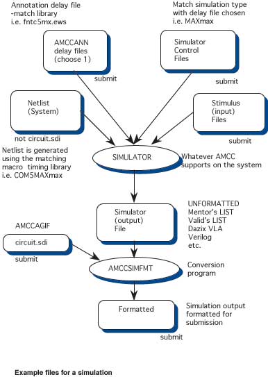
AMCCVRC will also identify primary signals that did not change in both directions during the vector set (toggle test). It produces a report and error listing called AMCCVRC.LST that is a required part of the design submission package.
Every maximum worst-case functional simulation file must be processed through AMCCSIMFMT and AMCCVRC.
| simulator output | ----> AMCCSIMFMT formatter ---> | amccvrc.lst AMCCVRC Report |
Copyright © 1996, 2001, 2002, 2008, 2016 Donnamaie E. White , WhitePubs
Enterprises, Inc.
For problems or questions on these pages, contact [email protected]