Logic Design for Array-Based Circuits
by Donnamaie E. White
Copyright © 1996, 2001, 2002, 2008, 2016 Donnamaie E. White, WhitePubs Enterprises, Inc.
- Table of Contents
- Preface
- Overview
- Chapter 1 Introduction
- Chapter 2 Structured Design Methodology
- Chapter 3 Sizing the Design
- Chapter 3 Appendix = Case Study in Sizing a Design
- Chapter 4 Design Optimization
- Chapter 5 Timing Analysis
for Arrays
- Introduction
- Path Propagation Delay Overview
- Intrinsic Set-Up and Hold Time
- Intrinsic Recovery Time
- Set-up, Hold and Recovery Specifications
- Maximum Operating Frequency; Toggle Frequency
- Intrinsic Pulse Width
- Interconnect Delays
- Types of Extrinsic Loading
- Annotation
- Manual Computation - One Method
- Example Equations for Extrinsic Loading - Internal Nets
- Lnet - Front Annotation
- Fan-In
- Fan-Out - Lfo
- WireOR - Lwo
- k-Factors
- Computing Lfo
- Computing Lwo
- Computing Lnet
- Exercises
- Example Equations for Extrinsic Loading - Output Nets
- Q5000 Example (Front-Annotation)
- Worst-Case Delay Multiplication Factors
- Exercises
- Front Annotation
- Remedial Steps - When a Path is too slow
- Intermediate Annotation
- Remedial Steps - Intermediate Annotation
- Back Annotation
- Remedial Steps - Back-Annotation
- Exercises
- Chapter 6 External Set-up and Hold Times
- Chapter 7 Power Considerations
- Case Study: DC Power Computation
- Case Study: AC Power Computation
- Chapter 8 Simulation
- Case Study: Simulation
- Chapter 9 Faults and Fault Detection
- Chapter 10 Design Submission
- ASIC Glossary
Timing Analysis for Arrays
Last Edit July 22, 2001
Worst-Case Delay Multiplication Factors
Once the sum of all the typical intrinsic and extrinsic propagation delays in a circuit or path segment is computed and adjusted for the output capacitive load, then the result must be multiplied to obtain the worst-case delay as follows:
Tpdworst-case = Tpdtypical * adjustment
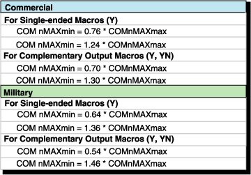
To perform worst-case analysis, the worst-case multipliers or adjustment factors for the appropriate operating range must be used. Example bipolar array multipliers are shown below. Refer to the appropriate design manual for worst-case multipliers for a particular array series.
Many vendors specify a typical propagation delay, with or without assumed loading. Delays due to fan-out loads are also given for specific conditions. When the power supply or temperature varies from the typical specification, some derating must be applied to the typical delays. In addition, some allowances for process variations should be made.
Some vendors specify the derating required for each of these items as a separate number or curve while others provide a combined worst-case multiplier, designed to assume that everything is in the worst possible state.
There may different derating or worst-case multipliers for macros and for the interconnect nets, and there may be different multipliers for different macros.
For a given array, the designer needs to determine whether the worst-case delay multipliers apply to set-up, hold, recovery time or pulse width.
Array Series (Historical) Timing Adjustment Factors - Different Arrays

![]()

Examples
The Raytheon design manual uses charts and shows a variation for temperature
derating that spreads from 0.88 for -25
AMCC specifies a worst-case military maximum derating factor of 1.45 for its bipolar arrays and specifies a process variation of 1.19 - 1.45 (20% variation) in combination with the temperature and voltage variations. The AMCC multipliers also account for temperature, voltage and process. The minimum operating conditions use a worst-case range of 0.70-0.89.
They apply to both the intrinsic macro delays (tin = Tpd) and to the extrinsic loading delays (tex), both loading delays on internal nets and loading delays on output macros due to capacitive load.
For interconnect delays, Raytheon provides tables to allow an estimate of fan-out delays based on fan-out load. They appear to be appear linear. (See Table 5-5.) Additional tables provide derating factors to allow adjustment for metal interconnect and metal temperature.
Table 5-5 Raytheon Adjustment Factors Factor/Variation (Historical)
| Temperature | 0.88/-25oC | 1.05/130oC | 1.15/150oC | |
| Voltage | ECL10K | 0.98/-5.2V | 1.05/-4.68V | |
| ECL100K | 0.98/-4.95V | 1.05/-4.05 | ||
| Process | 0.73 | 1.2 | ||
| TOTAL | 0.63 MIN | 1.449 MAX |
AMCC uses a non-linear equation to compute net loading and uses the macro worst-case multipliers on the interconnect delays.
For older arrays, AMCC also specified a linear relationship based only on fan-out loading (0.5ns/load for rising edge; 1.0ns/load for falling edge), also combined with the macro worst-case multipliers.
For the new BiCMOS series, the different technologies make different multipliers necessary. There is one for the bipolar interface macros and their extrinsic delays and one for the internal CMOS core macros and their extrinsic delays. The internal core macro worst-case multipliers apply to the set-up, hold, recovery time and pulse width values. An array series may have different multipliers for different arrays within the series.
Always verify the multipliers required, if any, and verify when they are used.Always go back to the latest information from the array vendor. |
Copyright © 1996, 2001, 2002, 2008, 2016 Donnamaie E. White , WhitePubs
Enterprises, Inc.
For problems or questions on these pages, contact [email protected]