Logic Design for Array-Based Circuits
by Donnamaie E. White
Copyright © 1996, 2001, 2002, 2008, 2016 Donnamaie E. White, WhitePubs Enterprises, Inc.
- Table of Contents
- Preface
- Overview
- Chapter 1 Introduction
- Chapter 2 Structured Design Methodology
- Chapter 3 Sizing the Design
- Chapter 3 Appendix: Case Study in Sizing a Design
- Chapter 4 Design Optimization
- Introduction
- Optimization Approaches
- Design for Speed
- Design to Improve Speed
- Macro options
- Macro functionality
- Example of silicon efficiency
- Alternative implementations
- Internal Net Delays
- Wire-ORs when allowed
- Design to Reduce Internal Cell Utilization
- Design to Reduce I/O Utilization
- Design to Fit the Package
- Example
- Design to Reduce Power
- Design to Reduce Cost
- Basic Design for Circuit Testability
- Basic Design for Circuit Reliability
- Design to Reduce Cost
- Exercises
- Chapter 5 Timing Analysis for Arrays
- Chapter 6 External Set-up and Hold Times
- Chapter 7 Power Considerations
- Case Study: DC Power Computation
- Case Study: AC Power Computation
- Chapter 8 Simulation
- Case Study: Simulation
- Chapter 9 Faults and Fault Detection
- Chapter 10 Design Submission
- ASIC Glossary
Design Optimization
Last Edit July 22, 2001
Design To Reduce Internal Cell Utilization
Reduction of the internal cell utilization or equivalent gate count is also called logical circuit minimization. Factoring of common terms from the logical equation and the removal of redundant logic help reduce cell counts by reducing the logic that must be implemented. Minimization is critical when a high fault-grade score is desired since redundant logic will lower the potential test score (fault masking).
Use of the higher functionality MSI macros and the design approach discussed earlier, of selecting higher functionality macros first and working back towards the SSI macros in the library, will contribute to a cell-efficient design. The design approaches for internal cell minimization are shown in Table 4-6.
Table 4-6 Minimizing Internal Cell Utilization
| Reducing Internal Cell Utilization |
|---|
| Logic minimization. |
| High-functionality internal macros. |
| Use shift counters instead of parallel counters. |
| Use ripple counters if the propagation delay meets specification delays. |
| Use ripple-carry adders (between MSI blocks). |
| Use single polarity between macros. |
| Use serial data transfer. |
| Use a scan-test F/F or latch to replace a MUX-F/F or MUX-LATCH combination. |
| Avoid extraneous invertors (those added just to invert signals).
Many macros are available in complementary form or use DeMorgan's theorem. |
| When converting from TTL or ECL, do not implement unused functions.
Keep the macro design application-specific. |
Avoid:
|
Internal cell minimization is not fully compatible with the approaches used to improve speed. While logic minimization does help speed, as does the use of high-functionality macros, serial operations are slower than parallel operations. The designer must be guided by the priority assigned to the conflicting design objectives.
Example
An experienced ECL designer chose the Q3500 array and converted a standard-part design into macros from the chosen library. He was careful to duplicate the parts exactly. When he was finished, he had 124% cell utilization. At the time, there was no larger array.
The solution came when the logic was minimized and the unused functionality of the individual standard parts was deleted from the design. By changing the design from a direct conversion to an application-specific implementation, the cell utilization was reduced to 98% and the circuit was built. {True story.}
Figure 4-3 Optimization - Cell Utilization (Sizing)
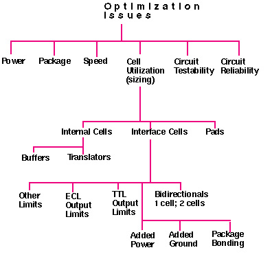
Optimization Issues - Cell Utilization
Copyright © 1996, 2001, 2002, 2008, 2016 Donnamaie E. White , WhitePubs
Enterprises, Inc.
For problems or questions on these pages, contact [email protected]