Bit-Slice Design: Controllers and ALUs
by Donnamaie E. White
Copyright © 1996, 2001, 2002, 2008 Donnamaie E. White
- Pre-Introduction
- Selection of the Implementation
- Microprogramming
- Advantages of LSI
- The 2900 Family
- Language Interrelationships
- Controller Design
- Constructing the CCU
- Sequential Execution
- Multiple Sequences
- Start Addresses
- Mapping PROM
- Unconditional Branch
- Conditional Branch
- Timing Considerations
- Pipelining
- Improved Architecture
3. Adding Programming Support to the Controller
- Expanded Testing
- Subroutines
- Nested Subroutines
- Stack Size
- Loops
- Am29811
- Am2909/11
- CASE Statement (Am29803A)
- Microprogram Memory
- Status Polling
- Interrupt Servicing
- Implementation - Interrupt Request Signals
- Vector Mapping PROM
- Next Address Control
- Am2910
- Am2910 Instructions
- JZ, CONT, JMAP
- CJP, CJV, LDCT, JRP, CJS
- JSRP, CRTN, RPCT, PUSH
- LOOP, CJPP, TWB
- Control Lines
- Interrupt Handling
- Am2914
- Interconnection of the Am2914
6. The ALU and Basic Arithmetic
- Further Enhancements
- Instruction Fields
- Instruction Set Extensions
- Sample Operations
- Arithmetic -- General
- Multiplication with the Am2901
- Am2903 Multiply
Refining the CCULast Edit November 2, 1996; May 1, 1999; July 7, 2001 Interrupt ServicingUnder interrupt servicing, the controlling unit stops to service an I/O only when an interrupt request is detected. There are two basic variations of this scheme - polled interrupt and vectored interrupt. Polled InterruptWith polled interrupt, all of the interrupt request lines are ORed into one interrupt request signal, and the controller tests this line periodically. When a request is detected, the controller stops and then polls each device to determine which device made the request. Priority is assigned by the position of the device in the polling sequence.
Vectored InterruptWith vectored interrupt, all of the device interrupt request lines are ORed as with polled interrupt. This time, however, when a request is sensed, the interrupt is identified to the controller. A priority scheme may or may not be involved.
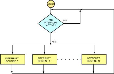
A microprogram flowchart is given in Figure 4-2. Figure 4-2 Interrupt vectoring microprogram flowchart. One microinstruction interrupt supplies the branch address for the routine.
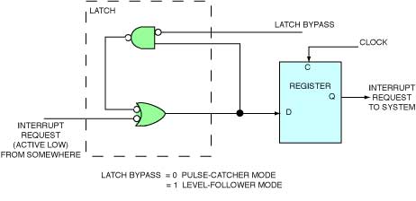
Implementation - Interrupt Request SignalsThere are two types of interrupt request or device service request signals - level sensitive and edge sensitive. Level sensitiveLevel sensitive signals are generally device generated. The device raises (or lowers) its request line until the system acknowledges the signal. On receipt of the system acknowledge, the device drops its request. Edge sensitiveEdge sensitive or pulse signals are generally initiated by a transient event occurrence. The pulse may occur one or more times and must be "caught" by the interrupt detection hardware on its first occurrence. Interrupt StorageA single interrupt store circuit involving a latch and register is shown in Figure 4-3. By setting the latch bypass control at 1 or 0, the circuit is level-driven or acts as a pulse-catcher. Once the interrupt requests are clocked into the register, the register output is an interrupt request signal for the system. Figure 4-3 Single Interrupt Storage. Latch bypass = 0, pulse catcher =1, level driven
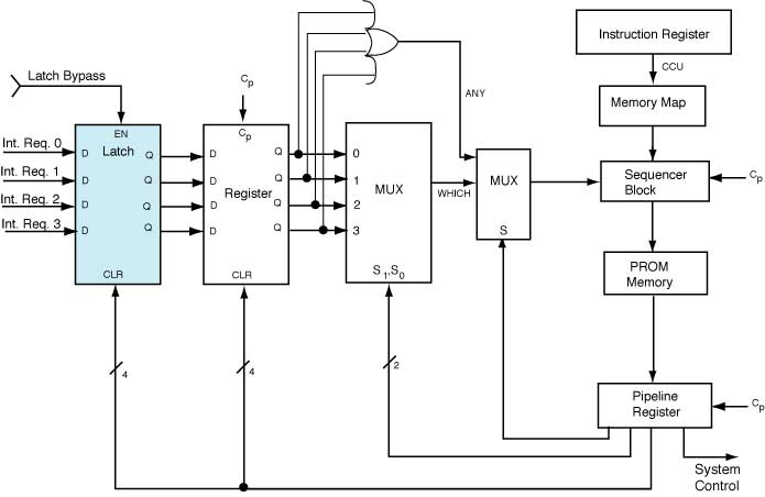
Implementing Polled InterruptPolled interrupt might be implemented by inputting the interrupt request lines to a multiplexer and then outputting that MUX output into the conditional test MUX of the control unit, or directly into the output enable (OE') of the Am2910, for example. The outputs of the register are also fed into an OR gate, which is another input to the conditional test MUX. When a test is made of the OR input and it is found (that an interrupt exists) a branch is made in the microprogram to an interrupt polling routine. This routine is a series of test and branch instructions, where each microinstruction selects one of the interrupt request line to test (see Figure 4-4). Figure 4-4 Polling Interrupt Request lines via MUX. Each microinstruction increments S1S0 index to examine next request line.
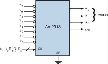
In either case, there is a limit on the number of interrupts that can be handled and a high overhead in the microword widths and the microroutine length (and, therefore, a large microprogram memory) to provide for the desired number of allowable interrupts. Implementing Vectored InterruptWith vectored interrupt, an OR gate is still involved and still feeds into one input of the conditional test MUX. However, the interrupt or device identification is provided to the system without further demands on the available MUX inputs. One scheme for identification of the interrupt is to use a priority encoder such as the Am2913. This device accepts eight interrupts (active low) and outputs a 3-bit vector, which is the binary index of the highest priority interrupt line. It also outputs a fourth signal, which is the OR gate, i.e., ANY. The logical block is shown in Figure 4-5. Figure 4-5 Am2913 priority interrupt encoder/expander (limited expansion). If Y7 low, output is (111)2, all other Yi are "don't care". A2A1A0 represents the index of the highest priority interrupt received. This is the address or address modifier for the service routine.
The index itself is a partial address, and there are various schemes that could be used. Two are considered here. The three bits could be a complete start address, with zeros driven into low-order bit locations. This fixes the areas within the microprogram memory where the start address of the appropriate service routines may be placed. The three bits could be a complete address into the lower address portion of the micromemory, with an interrupt jump table stored there. This frees the routine to be placed anywhere but requires that the first few words of the micromemory be reserved for the jump table.
|


