Bit-Slice Design: Controllers and ALUs
by Donnamaie E. White
Copyright © 1996, 2001, 2002, 2008 Donnamaie E. White
- Pre-Introduction
- Selection of the Implementation
- Microprogramming
- Advantages of LSI
- The 2900 Family
- Language Interrelationships
- Controller Design
- Constructing the CCU
- Sequential Execution
- Multiple Sequences
- Start Addresses
- Mapping PROM
- Unconditional Branch
- Conditional Branch
- Timing Considerations
- Pipelining
- Improved Architecture
3. Adding Programming Support to the Controller
- Expanded Testing
- Subroutines
- Nested Subroutines
- Stack Size
- Loops
- Am29811
- Am2909/11
- CASE Statement (Am29803A)
- Microprogram Memory
- Status Polling
- Interrupt Servicing
- Implementation - Interrupt Request Signals
- Vector Mapping PROM
- Next Address Control
- Am2910
- Am2910 Instructions
- JZ, CONT, JMAP
- CJP, CJV, LDCT, JRP, CJS
- JSRP, CRTN, RPCT, PUSH
- LOOP, CJPP, TWB
- Control Lines
- Interrupt Handling
- Am2914
- Interconnection of the Am2914
6. The ALU and Basic Arithmetic
- Further Enhancements
- Instruction Fields
- Instruction Set Extensions
- Sample Operations
- Arithmetic -- General
- Multiplication with the Am2901
- Am2903 Multiply
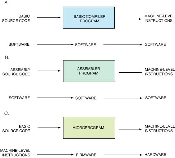
IntroductionLast Edit October 10, 1996; July 9, 2001 Language InterrelationshipsProgramming classes relate source code - written by the user in some programming language - to object code - the machine level - machine executable instructions - via an assembler or compiler. A compiler is a software program that translates a high-level (compiler level) language program into object code. An assembler is a software program that translates an assembly-level source program into object code. There are usually several compilers and one assembler per computer system. Compilers translate at an average ratio of four to one (four machine instructions per source instruction [as in FORTRAN IV]) or higher (six to one for FORTRAN VI). Assemblers can be very nearly one to one, with assembly statements being a mnemonic form of the bit pattern machine instruction. In both cases, software is processed by software to produce software, as shown in Figure 1-3. Figure 1-3 Language relationships
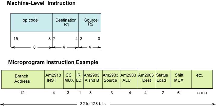
High-Level LanguageHigh-level languages are fairly free format, i.e., they have few columnar placement restrictions on the coding form (free-form), use pseudo-English mnemonics (LET, GOTO, IF), and have prewritten functions. Their capabilities include arrays, loops, branches and subroutines, with the emphasis on structured programming support with IF-THEN-ELSE, CASE and PROCEDURE statements. Assembly Level LanguageAssembly-level languages have a more restricted format, require a precise data definition, may involve the programmer in program placement in memory, and use mnemonics for instructions but have more of them. Most instructions or statements are restricted to one operation - hence the approximate one to one translation ratio. The assembly level programmer in general must know more about the machine being used than the programmer who writes in FORTRAN or BASIC. Machine Level LanguageMachine-level languages are the closest to the system of the software level languages. They are usually written using an encoding of instructions, data and addresses in either octal or hexadecimal notation, are more tedious to construct and debug and are more restrictive in the format required than the assembly level languages. They can require more specific detail from the programmer, depending on the complexity of the system being programmed. MicroprogrammingThe machine level instructions are what the computer control unit (the CCU) receives. In a microprogrammed machine, each machine level instruction (referred to as a macroinstruction) is decoded and a microroutine is addressed which, as it executes, sends the required physical control signals in their proper sequence to the rest of the system. This is where the software instruction via a firmware microprogram is converted into hardware activity. Microprogram StorageThe various software programs will vary from hour to hour, or more often, and their data will vary; therefore read-write or RAM memory is required as their storage area. The microprogram, however, will usually remain the same. There are a few machines - the Burroughs 1700, for example - that loaded a different microprogram for each of several specific application languages. Where one microprogram is to be used by the system, ROMs (high-production) or PROMs (lower production, prototype) are used for the microprogram memory. Such systems are called microprogrammed systems. When a microprogram may be replaced by another, for example, to emulate another machine or to do a diagnostic run, then either a separate read-write memory, called a writeable control store (WCS), or part of the system main memory is used as the microprogram memory with minifloppies, tape cartridges, or an area of main memory as the auxiliary storage for the microprograms. The alterability is attractive for special application systems such as experimentation control. Writ able control storage is also useful for prototype systems and is present on development systems for flexibility. Systems with alterable microprograms are called microprogrammable systems. Throughout the remainder of this text, the microprogram control memory will be assumed to be a PROM memory for the sake of simplicity. FormatEach machine-level instruction is in the form of an opcode and operands. There may be several different formats for the instructions in any one machine. These instructions are decoded by the control unit, and the decoding produces an address which is used to access the microprogram memory. The microroutine for the individual machine or macroinstruction is called into execution and may be one or more microinstructions in length. (A microinstruction will be assumed to execute in one microcycle, also for simplicity.) Each microinstruction field directs or controls one or more specific hardware elements in the system. Every time that a particular machine instruction occurs, the same microroutine is executed. The particular sequencing of the available microroutines constitutes the execution of a specific program. Machine level language is very close to the hardware and has a very constrained format. It uses no mnemonics and requires that everything be specified by the programmer, including program address and data addresses. A sample machine instruction is shown in Figure 1-4A. More than one machine instruction format usually exists for a given system. The machine decodes which format it is using for part of the microinstruction via the content of other certain specific fields. Figure 1-4 sample formats (A) sample machine level instruction (register addressing) (B)sample microprogram instruction (Am2900 family). Address (adr), condition code (CC), destination address (Dest), instruction (Instr), R1 and R2 are operands.
Microprogramming is done in the format or formats designed by the programmer. Once chosen, the format becomes fixed. Each field controls a specific hardware unit or units and the possible bit patterns for each field are determined by the signals required by the hardware units being controlled. Simple, short microprograms can be recorded in bit string fashion and prototype PROMs created using manually operated PROM burners. A sample microinstruction format is shown in Figure 1-4B. More than one microinstruction format can exist for a given microprogram. When two or more exist, extra bits must be added to the microword and these are assigned the task of signaling the controller as to which format is being decoded. Development systemsLonger microprograms (more than 32 microwords in length or with microwords more than 16 bits wide) are better handled with a development system. These systems allow each field to be defined in mnemonics, which is a documentation aid. Once the fields are thus defined, the microcode (microprogram, microroutines, microinstructions) can be written in mnemonics, more or less in a pseudo-assembly language (called a meta language) providing human-readable self-documenting code in the process. The development system then may be used to assemble the microprogram and create the input to an automated PROM burner. The development systems allow prototype hardware to be connected to them, and with the prototype microprogram load in the writeable control store of the development system, the development system can be used to debug hardware and firmware in parallel. The WCS is used to replace the microprogram control store of the prototype system. For the 2900 Family, the development system is the Advanced Micro Computer AmSYS 29TM. (Neither Advanced Micro Systems - a Seimens - AMD venture - nor the AmSYS29 survives.) Microprogramming is the programming level closest to the hardware, and the microprogrammer must know everything about each of the pieces of hardware which are to be controlled. The trade-off here is between the detail level of the programming and the power and the control of the hardware that is possible. The actual number of microroutines required is a function of the number of machine-level instructions that the system is to recognize. For an average computer (circa 1985), there would be about four microinstructions per machine instruction, with the minimum being 1 and the maximum at 16. The average varies with the application. Figure 1-5 gives the relative relationships between the ease of programming and the level of control provided by each of the language levels. C+ and its derivatives evolved because of the need to have access to machine-level control of the hardware, while still being able to describe algorithms in a higher-level programming code, a hybrid of both worlds. Microcoding, a.k.a. writing Firmware, equires a detailed knowledge of the hardware, time to write the program, and power and control of the hardware. Higher level languages are removed from the actual bit-switching. Figure 1-5 Language interrelationships.
|


